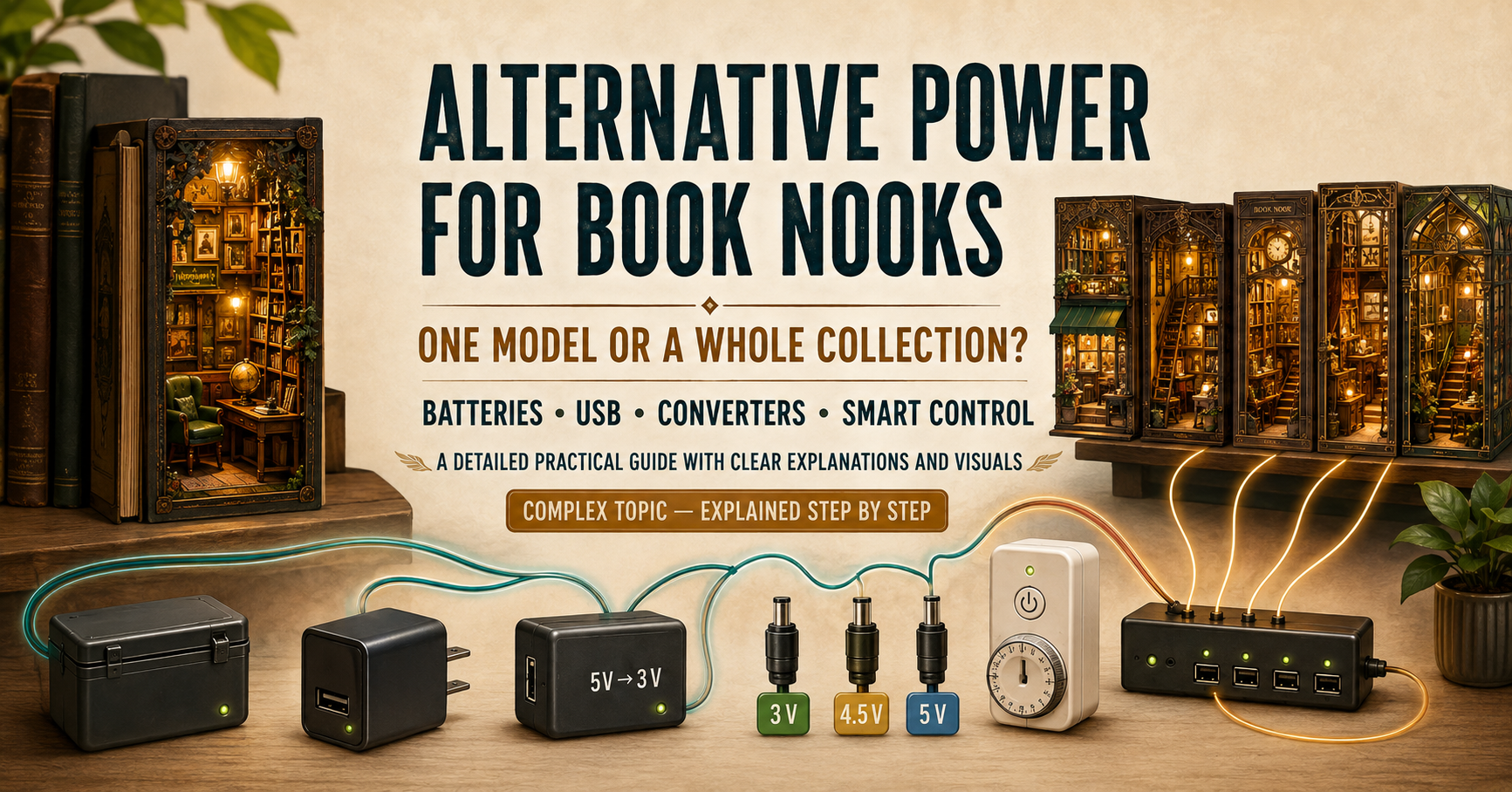
written by Martin Seidler based on own experience, experience of Terra Elsberry and external internet sources
Battery-powered lighting is convenient while building a book nook, but it becomes much less practical once you have a larger permanent collection. Batteries need to be replaced, battery boxes occupy valuable space, and reaching them inside a completed model may be difficult.
Many builders therefore look for ways to power their book nooks from USB chargers, wall adapters, smart plugs or one central power supply. This is certainly possible, but there is no universal solution suitable for every model.
The correct method depends on:
- The voltage originally supplied by the batteries
- The number of book nooks connected
- Their combined current consumption
- The number and type of LEDs
- Touch sensors and lighting modes
- Motors, sound modules and animated mechanisms
- Whether the original controls should remain functional
- Whether the book nooks should switch on automatically
- Whether they will be controlled through a smart plug, timer or central switch
Replace the battery voltage—not merely the battery shape or connector.

1. First determine the original voltage

| Original power source | Typical nominal voltage | External-power starting point |
|---|---|---|
| 2 × AA batteries | 3 V DC | Regulated 3 V supply or 5 V-to-3 V converter |
| 2 × AAA batteries | 3 V DC | Regulated 3 V supply or 5 V-to-3 V converter |
| 3 × AA batteries | 4.5 V DC | Regulated 4.5 V preferred; carefully tested 5 V USB often works |
| 3 × AAA batteries | 4.5 V DC | Regulated 4.5 V preferred; carefully tested 5 V USB often works |
| One 3 V coin cell | 3 V DC | Additional circuit and current assessment required |
| Factory USB or USB-C input | Usually 5 V DC | Use the factory input with a suitable 5 V USB supply |
Before buying an adapter or cutting any wires, inspect the original battery arrangement.
AA and AAA alkaline batteries have the same nominal voltage. Their principal differences are physical size and capacity.
Rechargeable NiMH batteries normally provide approximately 1.2 V per cell rather than the 1.5 V nominal voltage of alkaline batteries. Most book nooks designed for ordinary AA or AAA batteries tolerate this difference, but it should still be considered when diagnosing unusual behaviour.
Coin-cell-powered models require additional caution. Although a coin cell may be marked 3 V, it can provide only a relatively small current. Replacing it with a powerful 3 V adapter is not automatically safe if the original circuit relies partly on the coin cell’s limited current capability.
The battery count is not always the complete answer. Before removing the battery box, check whether it also contains:
- An on/off switch
- Resistors
- A touch-control board
- A transistor or MOSFET
- A motion sensor
- A timer or lighting controller
- Connectors
- Motor, sound or animation electronics
In some kits, the battery box is only a holder. In others, it is an integral part of the control system. Cutting it away without inspecting it may remove more than just the batteries.
If possible, photograph the original wiring and measure the polarity and output voltage with a multimeter before making any changes.
2. Can a standard 5 V USB supply power a typical book nook?

In some cases, yes, BUT:
A three-battery book nook is nominally rated for 4.5 V, while a normal USB supply provides approximately 5 V. This is an increase of about 11%, which is very different from connecting 5 V to a two-battery 3 V model—an increase of approximately 67%.
Fresh alkaline batteries can also measure around 1.6 V each before their voltage falls under load. Three fresh cells may therefore approach 4.8 V, already quite close to a 5 V USB supply. Energizer’s technical guidance explains both the fresh open-circuit voltage and the voltage reduction caused by battery internal resistance under load.
| Original arrangement | Difference when using 5 V | Practical assessment |
|---|---|---|
| 2 batteries: nominally 3 V | Approximately +67% | Substantial risk; use a regulated 3 V supply or converter |
| 3 batteries: nominally 4.5 V | Approximately +11% | Often acceptable, particularly for simple LED-only circuits |
| 3 fresh cells at approximately 4.8 V | Approximately +4% | Very small difference |
This explains why many builders—including the author—have successfully powered three-battery book nooks directly from standard 5 V USB supplies. The model may shine slightly brighter but continue operating without any apparent problem.
There are nevertheless several qualifications:
- A USB supply is regulated and normally has much lower internal resistance than batteries. It continues holding approximately 5 V instead of gradually dropping as batteries discharge.
- Brighter LEDs indicate increased current. This may not cause immediate failure, but it can reduce long-term LED life if the original circuit has very small current-limiting resistors.
- A USB output is not always exactly 5.00 V. Traditional USB specifications normally allow some variation around the nominal value.
- Motors may run slightly faster or noisier at 5 V.
- Touch, sound and animation controllers should be tested in every operating mode.
The practical recommendation is therefore:
- Simple 4.5 V LED-only book nook: Direct regulated 5 V USB is normally a reasonable solution after testing.
- 4.5 V model with a touch controller: Direct 5 V will often work, but test every mode and check whether any component becomes warm.
- 4.5 V model with motors, sound or animation: Direct 5 V may still work, but a regulated 4.5 V supply is preferable for valuable models, continuous operation or mechanisms that become faster or noisier.
- Any 3 V two-battery model: Do not apply 5 V directly. Use a regulated 3 V supply or converter.
For a 4.5 V model, treat direct 5 V USB as a practical, commonly successful option—not as a universal guarantee. Test brightness, every function and component temperature before using it permanently.
3. Find the right solution for your book nook
Use the interactive finder below to identify the most suitable power arrangement for your model and the functions you want to preserve.
Book Nook Power Solution Finder
Answer five questions to identify a suitable external-power arrangement for your model.
4. Quick reference: choose by desired result

| Desired result | Recommended solution | Smart-plug behaviour | Advantages | Limitations |
|---|---|---|---|---|
| Replace batteries while preserving touch control, modes, timer and other functions | Use a battery eliminator or feed the correct voltage at the original battery input. For a simple three-battery model, tested 5 V USB may also be used. | Remote OFF works. Remote ON may still require a touch, motion or mode command. | Preserves the original electronics and functions; usually reversible. | Power restoration may leave an electronic controller in its default OFF state. |
| Control a simple mechanical-switch model through a smart plug | Connect a suitable external supply at the battery input and leave the mechanical switch ON. | Normally provides predictable remote ON and OFF. | Simple and suitable for controlling several models together. | The voltage must still match the model. A local switch left OFF prevents remote activation. |
| Control a modern model with a factory USB input | Use its factory USB or USB-C input with a suitable 5 V supply. | If it illuminates automatically when power returns, smart control works directly. | Cleanest solution; no battery eliminator or converter required. | Power-on behaviour is model-specific and must be tested. |
| Use 5 V USB with a two-battery 3 V model | Install a regulated 5 V-to-3 V converter. | Depends on whether the original controller remains in the circuit. | Allows standard USB supplies to be used safely. | Direct 5 V is excessive for a 3 V model. |
| Use 5 V USB with a three-battery 4.5 V model | Direct 5 V is often practical for simple models; use a 4.5 V converter when maximum caution or exact voltage is required. | Depends on the original controller and its power-restoration behaviour. | Often avoids an additional converter; widely successful in practice. | LEDs may be brighter; motors and sensitive electronics require testing. |
| Use only central control, with no local functions | Supply the correct voltage directly to the load, bypassing only the control function. | Provides predictable central ON and OFF. | Useful for a synchronized permanent display. | Touch control, lighting modes and timers may be lost. Do not bypass LED-current limiting or motor/sound drivers. |
| Retain both battery and external-power operation | Use a removable connector, selector switch, switched socket or proper power-selection circuit. | Available while external power is selected. | Suitable for home use and exhibitions. | Batteries and external power must never be connected directly in parallel. |
5. Option one: a dummy-battery eliminator

For an already completed book nook, a battery eliminator is usually the easiest and least invasive solution.
A typical battery eliminator consists of:
- One powered dummy battery
- One or more passive dummy batteries
- A cable leading to a USB supply or wall adapter
- Electronics that reduce and regulate the incoming voltage
The dummy batteries are inserted into the original compartment in place of the real batteries.
Advantages
- No soldering is usually required
- The original battery box remains in place
- The original switch and controller are preserved
- Touch sensors and lighting modes remain available
- The conversion is reversible
- It can be installed in an already completed model
Disadvantages
- The cable must leave the battery compartment
- The battery cover may no longer close properly
- A small cable notch may be required
- AA and AAA eliminators are physically different
- The eliminator must match the original number of cells
- Product quality varies considerably
- Restoring power may not automatically switch on a touch-controlled model
Some inexpensive products are described as battery eliminators even though they do not provide properly regulated output. They may use only diodes, resistors or another crude voltage-reduction method. Their voltage may consequently change with the electrical load.
For a two-cell model, look for an eliminator explicitly providing a regulated 3 V output. For a three-cell model, a regulated 4.5 V eliminator is the technically exact choice, although direct 5 V USB is often a practical alternative as discussed above.
Confirm the physical battery size, number of dummy cells, output voltage, polarity, maximum current, cable position and cable length. Measure the output before installation and again while the model is operating.
6. Option two: replace or externally power the battery box

Some book nooks have a battery box connected through a removable two-pin plug. In these cases, the battery box can sometimes be unplugged and replaced with a suitable external power cable or power supply.
The replacement must match:
- Output voltage
- Connector type
- Connector pinout and polarity
- Wiring arrangement
- Any electronics built into the original battery box
The power supply must also provide sufficient current for the complete circuit. A higher current rating is acceptable because the book nook will draw only the current it needs.
For a two-battery model, use a regulated 3 V supply. For a three-battery model, use regulated 4.5 V if you want to match the original nominal voltage exactly. A regulated 5 V USB supply can be a practical alternative, but it should be tested carefully under full load. Check for excessive LED brightness, unstable operation or overheating.
Identical-looking two-pin connectors do not necessarily use the same polarity. Never assume that wire colours or connector orientation are consistent between manufacturers. Confirm the polarity with a multimeter and clearly label the replacement connector.
If the original battery box contains a switch, touch sensor or electronic controller, it may be better to retain the box and connect the external supply to its battery terminals after removing the batteries. Never apply external power while disposable batteries remain installed.
The opposite approach may be preferable if you want to control one or more book nooks remotely with a smart plug or timer. Many touch controllers return to the OFF state whenever power is disconnected, which prevents reliable external switching. In that situation, bypassing the touch controller may allow the book nook to switch on automatically whenever external power is restored. Be aware, however, that bypassing the controller may also remove dimming, lighting modes or other functions.
7. Option three: use USB with a voltage converter

This option is closely related to option two. Option two explains where and how external power is connected to the book nook. This option explains how standard 5 V USB power can first be converted to the voltage required by the model.
The complete arrangement is:
USB power source → voltage converter, if required → suitable connection → book nook
USB power is widely available and convenient. It works well with multiport chargers, timers and smart plugs.
For a two-battery model, the correct arrangement is:
5 V USB → regulated 3 V converter → suitable connection → book nook
For a three-battery model, there are two reasonable approaches:
Exact-voltage approach:
5 V USB → regulated 4.5 V converter → suitable connection → book nook
Practical direct approach:
Regulated 5 V USB → suitable connection → book nook originally designed for 4.5 V, after careful testing
The converter is preferred for complex, valuable or continuously operated models. Direct 5 V may be acceptable for a simple LED-only three-battery book nook, but the complete model should first be tested under full load. Check LED brightness, controller operation, sound, motors and any components that may become warm.
How is the converter connected to the book nook?
The output side of a voltage converter is normally a two-wire low-voltage DC connection. It must be connected to the book nook using one of the methods described in the previous section:
- If the battery box has a removable two-pin plug, the converter can be fitted with a matching connector and plugged directly into the book nook. The connector type, polarity and wiring must be verified.
- If the original switch, touch sensor or controller is built into the battery box, retain the box and introduce the converted voltage at the empty battery terminals.
- If the battery box is hardwired, the converter must be connected at the battery terminals or incorporated into a properly insulated modification of the original wiring.
Never connect external power while batteries remain installed.
If the battery box is removed completely, any switch, touch sensor or controller contained inside it will also be removed from the circuit. This may be intentional when using a smart plug or timer, particularly if the original touch controller always returns to the OFF state after power is disconnected. However, bypassing the controller may also remove dimming, lighting modes or other functions.
Possible converter solutions include a commercial fixed-voltage converter cable, a fixed-output buck converter, an adjustable buck converter, a suitable voltage regulator or a purpose-built lighting controller. The selected converter must be designed to provide the required output voltage from a 5 V input and must have sufficient current capacity for the complete model, including the starting current of motors or sound modules.
An adjustable converter must always be set and measured before it is connected to the book nook. Some modules arrive at an unknown output voltage, and the adjustment can move during handling or installation. Measure the output again after installation and before connecting the model.
A resistor is not a reliable universal substitute for a voltage converter. The voltage dropped across a resistor depends on the current being drawn, which may change when lighting modes, motors or sound are activated.
USB-C does not automatically make a battery-powered model compatible with 5 V. USB-C describes the connector and supported power-delivery arrangements; it does not change the voltage required by the book nook’s battery circuit.
If the book nook already has a manufacturer-installed USB-C input, that socket should normally receive the voltage specified by the manufacturer. Do not connect the 3 V or 4.5 V output of a converter to the book nook’s USB-C socket. When converting a battery-powered model, the reduced-voltage output must instead be connected to the battery circuit or to the verified battery-box connector.
8. Touch sensors and smart plugs

Capacitive touch sensors can normally operate from an external supply, but they may behave differently than when powered by batteries.
An electrically noisy or poor-quality adapter can cause false activations, reduced sensitivity, flickering, unpredictable switching or complete failure to respond. Long cables and some switching converters can also introduce electrical noise.
Use a reputable supply, keep low-voltage wiring reasonably short and test the complete system before permanently closing the model.
Will a smart plug automatically turn the lights on?
Not necessarily. Actually, realistically it is very unlikely
A smart plug can restore power, but many touch controllers return to their default OFF state. The smart plug may therefore energize the controller without switching on the lights.
The available solutions are:
- Keep the touch controller and accept that manual activation may still be required
- Bypass only the control function and use the smart plug as the main switch
- Install a mechanical switch
- Use a purpose-built smart low-voltage controller
- Select models that automatically illuminate when power is restored
Do not bypass components that provide LED-current limiting, motor control, sound control or other essential functions.
9. Motors, sound and animation require greater caution

A simple group of static LEDs requires relatively little current. Motors, speakers, solenoids and animated mechanisms can create much larger and rapidly changing loads.
A motor may draw several times its normal running current when it starts or stalls. Sound modules and complex controllers may also create brief current peaks.
An underpowered or unsuitable supply may cause:
- Motors to start intermittently or run slowly
- Touch controllers to reset
- Sound modules to restart
- Lights to pulse or dim
- Converters to overheat
- The complete system to shut down
A higher current rating is normally acceptable. A 3 V, 2 A supply does not force 2 A through a model requiring only 100 mA. The model draws the current it needs.
The voltage remains the critical parameter. A motorized 4.5 V model may operate from 5 V, but listen for increased speed or noise and use a regulated 4.5 V supply if its behaviour changes noticeably.
10. Powering several book nooks from one supply

One power supply may operate one, two, five or even ten book nooks, but only if it provides suitable voltage to every model and sufficient current for their combined load.
The number of models alone is not enough information. One animated book nook may consume more power than several simple LED-only models.
More book nooks do not divide the voltage
Book nooks powered from one supply should normally be connected in parallel. In a parallel circuit, every model receives the same voltage as the source.
Therefore:
- Four models connected to a 5 V supply each receive approximately 5 V
- They do not receive 1.25 V each
- Adding more models does not make 5 V safe for 3 V electronics
- The models must never be connected in series to divide the voltage
The current demands are added together, but the voltage is not divided.
Never use an overloaded supply as a voltage converter
Some inexpensive or older unregulated adapters produce a higher voltage when lightly loaded and a lower voltage when several devices are connected. This can create the impression that an excessive supply becomes safe when additional models are attached.
This behaviour must not be used as a design method. The voltage may change whenever a light, motor, sound module or complete book nook is switched on or off.
A proper regulated supply attempts to maintain its specified voltage. If overloaded, it may limit current, allow its voltage to collapse, repeatedly restart, enter thermal protection or shut down.
Voltage dropping under excessive load is a warning that the supply, converter, cable or connector is inadequate. It is not a safe method of voltage regulation.
Understanding voltage and current ratings
A power supply marked 3 V, 2 A supplies 3 V and can provide up to 2 A. It does not force 2 A through every connected model.
| Book nook | Maximum current |
|---|---|
| Book nook 1 | 120 mA |
| Book nook 2 | 180 mA |
| Book nook 3 | 250 mA |
| Book nook 4 | 150 mA |
| Combined maximum | 700 mA |
After adding at least 25–30% reserve, a regulated supply rated for approximately 1 A or more would be appropriate.
The capacity of every stage must be considered. A 5 V, 3 A USB charger connected through a converter rated for only 500 mA can provide no more than the converter can safely handle.
With multiport USB chargers, check both the maximum output of each port and the maximum combined output shared by all ports.
Test the voltage under full load
Test the complete installation with every intended book nook connected and with all functions operating.
Measure the voltage:
- At the output of the main supply
- At the output of each voltage converter
- At the input of the most distant book nook
- With all lights, motors and sound functions operating
After the display has been running, check whether the supply, converters, cables, splitters, connectors, controllers or motors are becoming unusually warm.
Cable voltage loss should be minimized. It should never be deliberately used as a substitute for a proper voltage converter.
Mixed-voltage collections
A collection may contain 3 V two-battery models, 4.5 V three-battery models and modern 5 V USB-powered models.
A practical central system can use one reputable 5 V USB supply, with each model receiving an appropriate connection:
- Native 5 V USB models: Direct 5 V connection
- Two-battery 3 V models: Regulated 5 V-to-3 V converter
- Simple three-battery 4.5 V models: Direct 5 V may be used after testing
- Complex or valuable 4.5 V models: Regulated 5 V-to-4.5 V converter preferred
Label every connector with its voltage and polarity.
11. Retaining both battery and external-power operation

Some builders want to retain batteries for exhibitions while using external power at home.
Never connect the battery pack and external adapter directly in parallel. One source may feed current back into the other, potentially damaging the adapter, overheating or leaking the batteries, or damaging the model.
Safe approaches include:
- A battery/external-power selector switch
- A switched DC socket that disconnects the batteries when a plug is inserted
- A proper automatic power-selection circuit
- Manually disconnecting one source before connecting the other
- A removable connector accepting either the battery box or external supply
For most hobby installations, a removable connector is the simplest solution. Connect either the battery box or external supply—but never both simultaneously.
12. Power banks are not always suitable
A USB power bank may appear ideal for portable operation, but many power banks automatically switch off when the connected load is too small.
A book nook containing only a few LEDs may draw less than the power bank’s minimum detection threshold. The lights may consequently switch off after a few seconds or minutes.
Some power banks have a low-current or trickle-charging mode, but this mode may also have a time limit. Test the selected power bank with the actual model for the complete intended display period.
13. Recommended standard for a permanent collection

- Preserve the original electronics whenever possible.
- Add or retain a removable low-voltage power connector.
- Give every two-battery model regulated 3 V.
- Give three-battery models regulated 4.5 V when maximum caution is required, while recognizing that tested 5 V USB is often practical.
- Use the factory 5 V input on native USB models.
- Use individual converters where voltage requirements differ.
- Provide sufficient current capacity with at least 25–30% reserve.
- Connect all models in parallel.
- Label every connector with voltage and polarity.
- Control the display with a smart plug, timer or switched strip.
- Bypass touch controls only when automatic illumination is required and the circuit is fully understood.
14. Final safety checklist

- Count the original batteries.
- Confirm the original nominal voltage.
- Inspect whether the battery box contains control electronics.
- Photograph and record the original wiring.
- Record connector orientation and polarity.
- Select a suitable supply for the original voltage and circuit.
- For a three-battery model using direct 5 V, test brightness, temperature and every function.
- Confirm the current capacity of the supply and converter.
- Measure the new supply before connecting it.
- Remove all real batteries.
- Make the first test while the book nook remains open and accessible.
- Test every lighting mode, motor, sound function and animation.
- Measure the voltage again under full load.
- Check LEDs, boards, motors, cables and converters for unusual heat.
- Label the model’s required voltage and polarity.
- Never connect batteries and external power directly in parallel.
- Never rely on overload or cable resistance to reduce voltage.
- Never bring exposed 230 V wiring or unprotected mains components near the model.
Conclusion
Replacing batteries with external power can make a large book-nook collection much easier to operate, but the conversion should be treated as a genuine electrical modification rather than simply a change of connector.
There is no single solution suitable for every book nook. A simple LED model, a touch-controlled kit, an animated scene with sound and a modern USB-powered model may all require different approaches.
Direct 5 V USB should not be treated identically for every battery arrangement. It is a substantial overvoltage for a 3 V two-battery model, but only a modest increase for a nominally 4.5 V three-battery model. In the latter case, it often works perfectly well—particularly with simple LED circuits—provided the complete model is tested.
The central principles remain straightforward:
- Provide a suitable voltage for the model
- Preserve the original controller when its functions are required
- Size the supply for the combined maximum current
- Test the complete installation under full load
- Never rely on an overloaded supply to reduce excessive voltage
- Make modifications reversible whenever possible
Replace the battery voltage—not merely the battery shape.
When in doubt, measure first.
Technical references
- Energizer: Battery Internal Resistance
- USB-IF: USB 2.0 Specification
- Texas Instruments: Linear and Switching Voltage Regulator Fundamentals
- Keysight: Series and Parallel Circuits

Copyright Book Nook Workshop 2026 – All rights reserved. (Martin Seidler)
Leave a Reply